Description
Both the Compact and Master Alarm systems shall be an Amico Alert 2 series, complete with a five-year warranty.
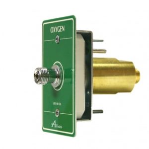
The Compact Alarm shall be microprocessor based with individual microprocessors on each display, sensor, and master boards. The sensors shall be capable of local (in box) or remote mounting. Each sensor and display unit shall be gas-specific, with an error message display for an incorrect connection.
The Compact Alarms shall be of modular construction and shall be field expandable with the addition of extra modules. Up to 12 services can be accommodated per standard box.
Each specific service shall be provided with an LED digital read-out comprising of 0-250 psi [1,724 kPa] for pressure and 0-30″ Hg [-100-0 kPa] for vacuum. The digital read-out shall provide a constant indication of each service being measured. A bar graph trend indicator shall be provided for each service indicating a GREEN NORMAL and a RED HIGH or LOW alarm condition. If an alarm occurs, the RED alarm led shall flash and the audible alarm will sound. Pushing the (mute button/push to test button) will cancel the audible alarm, but the unit will remain in the alarm condition until the problem is rectified.
The default set-points shall be /-20% variation from normal conditions. In the calibration mode, the following parameters shall be field adjustable: high/low set-points, imperial/metric units, repeat alarm enable/disable. Set-points shall be adjustable by two on board push buttons.
Each Master module shall be microprocessor based and field adjustable. Each signal contains a GREEN LED indicator for normal and a RED LED indicator for abnormal conditions. When a fault occurs, the green LED turns off, the RED LED illuminates and the audible alarm sounds. The RED LED flashes until the front panel alarm mute button is pressed. After the alarm mute button is pressed, the RED LED remains illuminated but does not flash. The red indicator automatically turns off and the GREEN LED illuminates when the fault is corrected. A repeat alarm function shall, when enabled, be capable of turning on the buzzer again after a preset time if the fault condition has not been rectified.
A maintenance mode shall, when enabled, latch the alarms, requiring a reset after the alarm condition has been rectified. This is to assist in tracking down wiring problems or faulty field devices. The master alarm shall identify the last alarm condition by flashing, while the already acknowledged alarm shows a continuous red signal. Each module shall handle 10 functions and up to 6 modules can be accommodated per standard box for a total of 60 functions. Master alarms shall be modular in construction and shall be capable of adding extra modules in the field.
The Alarm system shall be a closed circuit self-monitoring type. A GREEN POWER light shall provide indication that the unit is energized. In addition, TEST and ALARM MUTE buttons shall be easily accessible to operate and test the unit. Every master module shall be field upgradable to allow for interfacing to a building management system with the addition of an addon circuit board which plugs into the master module.
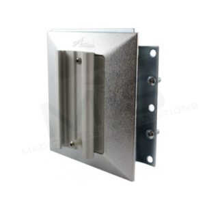
The frame assembly can be added to an existing alarm panel in the field with the addition of an extended mounting frame. The mounting frame is made from 18 gauge (1.3 mm) aluminum that has been painted for aesthetic appeal.
Input power to the Amico Alert-2 alarm is: 115 VAC – 220 VAC, 50 – 60 Hz.
Amico products comply with NFPA 99 and CSA Z7396.1.
The Amico Alert-2 Alarm complies with the following electromagnetic compatibilty standards: FCC Part 15 Class A and ICES-003 Class A.